DSBOARD-AGX Serial Communication Interfaces Tutorial
WHAT YOU WILL LEARN?
1- The pinout of I/O connector
2- Installing GtkTerm
3- Testing the serial communication interfaces
ENVIRONMENT
In this blog post, we will look at the pinout diagram of I/O connector on DSBOARD-AGX. Then, we will install GTKTerm serial connection application. Finally, we will test the RS232, RS422 & RS485 connections.
The Pinout of I/O Connector
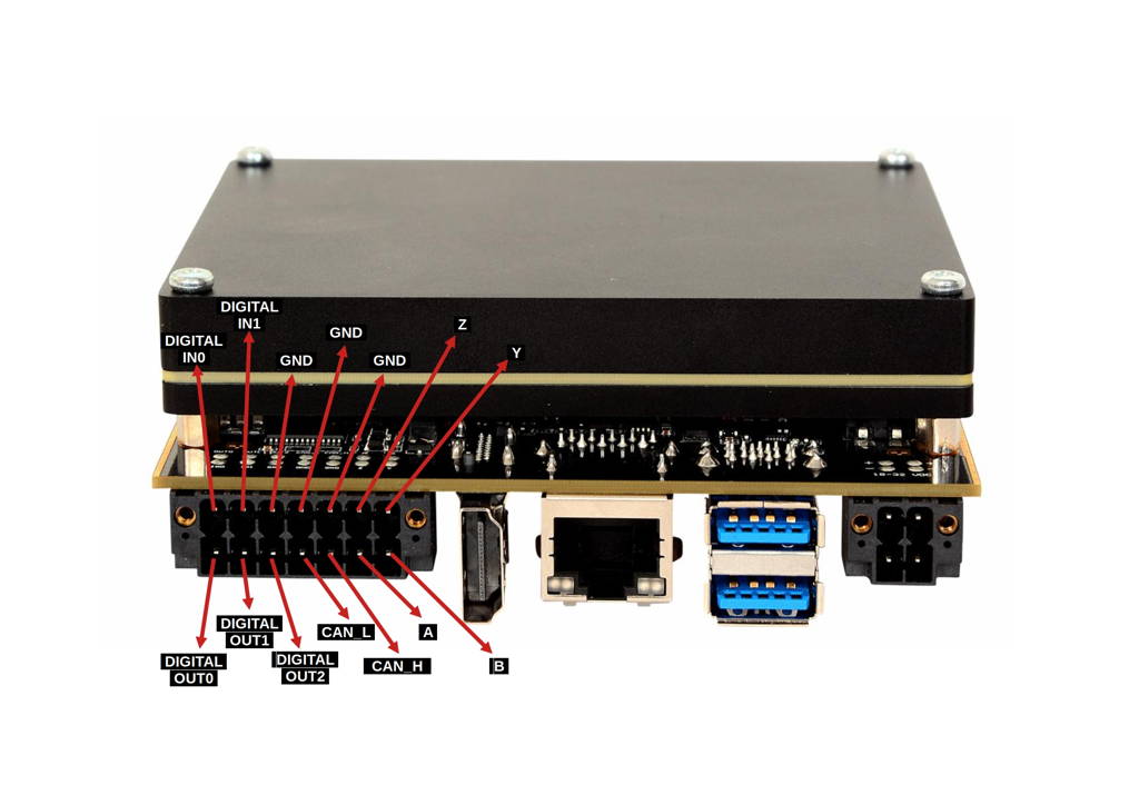
First, let's look over the IO connector. On the connector, there are 4 serial communication, 3 ground, 2 CANBus, 2 digital input and 3 digital output pins.
Installing GTKTerm
To test all serial communication interfaces, open a new terminal and install the GtkTerm program for ease of use (make sure Ethernet cable is connected). You can install GtkTerm with this terminal command:
sudo apt install gtkterm
Testing the Serial Communication Interfaces
Run the GtkTerm program with arguments. On the host side, you can use TeraTerm or Putty for Windows; GtkTerm for Ubuntu OS.

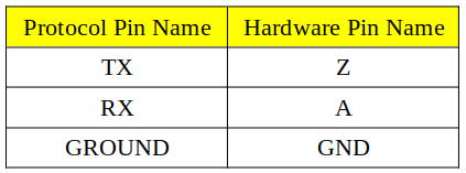
RS232 Test
To test RS232 functionality, we use a DSBOX-TX2NX as a test equipment. (If you use a USB-Serial adapter, connect that adapter to the USB port of the host PC and install its driver software if necessary.) To the other side of the connector, connect your device’s RS232 pins with cross-connection (Rx to Tx, Tx to Rx). You can find the hardware pins below.
After proper connection, you should do pin multiplexing on your device to use serial port as RS232.
To do this, open new terminal then type these commands below.
sudo sh -c "echo 428 > /sys/class/gpio/export"
sudo sh -c "echo 433 > /sys/class/gpio/export"
sudo sh -c "echo low > /sys/class/gpio/PM.04/direction"
sudo sh -c "echo low > /sys/class/gpio/PN.01/direction"
If you are using GtkTerm on Ubuntu, run this command below. If you have done everything correctly, you could see your keyboard presses on the other machine's serial terminal.
sudo gtkterm -p /dev/ttyTHS4 -s 115200
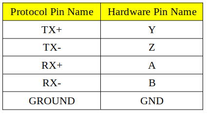
RS422 Test
To test RS422 functionality, we use a DSBOX-TX2NX as a test equipment. (If you use a USB-Serial adapter, connect that adapter to the USB port of the host PC and install its driver software if necessary.) To the other side of the connector, connect your device’s RS422 pins with cross-connection (Rx to Tx, Tx to Rx but positive to positive, negative to negative). You can find the hardware pins below.
After proper connection, you should do pin multiplexing on your device to use serial port as RS422.
To do this, open new terminal then type these commands below.
sudo sh -c "echo 428 > /sys/class/gpio/export"
sudo sh -c "echo 433 > /sys/class/gpio/export"
sudo sh -c "echo high > /sys/class/gpio/PM.04/direction"
sudo sh -c "echo low > /sys/class/gpio/PN.01/direction"
If you are using GtkTerm on Ubuntu, run this command below. If you have done everything correctly you could see your keyboard presses on the other machine's serial terminal.
sudo gtkterm -p /dev/ttyTHS4 -s 115200
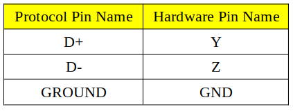
RS485 Test
To test RS485 functionality, we use a DSBOX-TX2NX as a test equipment. (If you use a USB-Serial adapter, connect that adapter to the USB port of the host PC and install its driver software if necessary.) To the other side of the connector, connect your device’s RS485 pins. You can find the hardware pins below.
After proper connection, you should do pin multiplexing on your device to use Serial Port as RS485.
To do this, open new terminal then type these commands below.
sudo sh -c "echo 428 > /sys/class/gpio/export"
sudo sh -c "echo 433 > /sys/class/gpio/export"
sudo sh -c "echo 344 > /sys/class/gpio/export"
sudo sh -c "echo high > /sys/class/gpio/PM.04/direction"
sudo sh -c "echo high > /sys/class/gpio/PN.01/direction"
To write data:
sudo sh -c "echo high > /sys/class/gpio/PEE.05/direction"
To read data:
sudo sh -c "echo low > /sys/class/gpio/PEE.05/direction"
If you are using GtkTerm on Ubuntu, run this command below. If you have done everything correctly you could see your keyboard presses on the other machine's serial terminal.
sudo gtkterm -p /dev/ttyTHS4 -s 115200 -w RS485
Thank you for reading our blog post.