RAIBOX-ORNX Industrial Input Output Interface Tutorial
WHAT YOU WILL LEARN?
1- The pinout of I/O connector
2- Setting and Reading Input Pin
3- Setting Digital Output as High and Low
ENVIRONMENT
In this blog post, we will test the IIO (Industrial Input-Output) interface of RAIBOX-ORNX.
The Pinout of I/O Connector
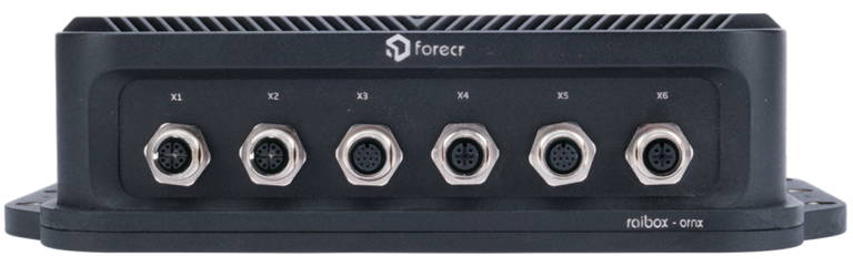
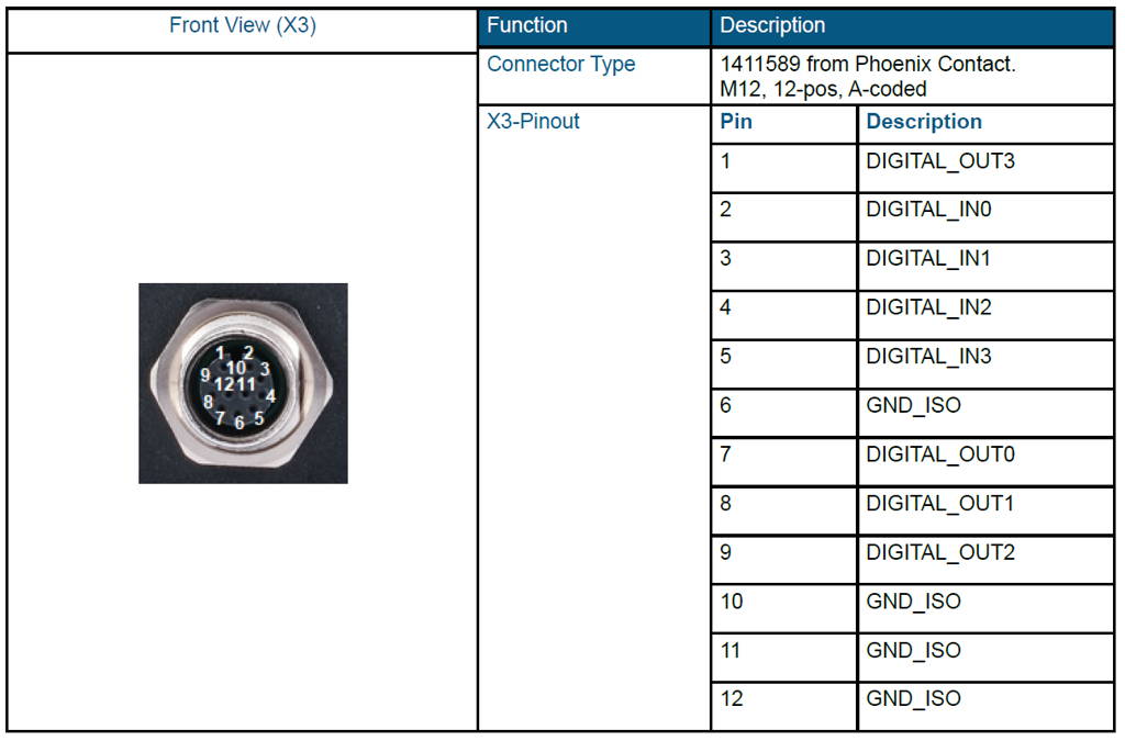
First, let's look over the 12 pin IO connector. On the connector, there are 4 ground, 4 digital input and 4 digital output pins.
Setting and Reading Input Pin
Digital input side accepts signals between 12-24V (rated for 2.25mA). In our application, we used Heschen M12 Inductive Proximity Sensor (PNP & Normally Open(NO)) with 24V voltage source.
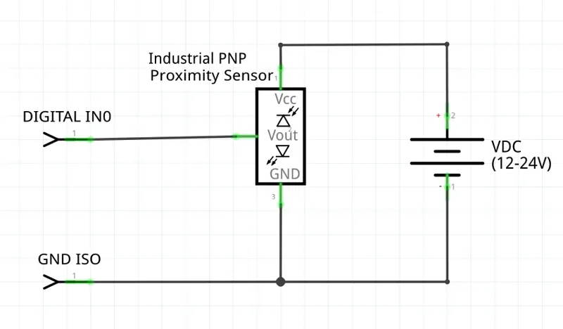
Find sysfs equivalent of the connected output pin from the table below. For this setup, it is DIGITAL_IN0. After proper hardware connection with industrial LED, we can continue with the software side.
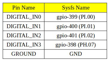
Set DIGITAL_IN0 as input and read sensor value. To do this, you should use the commands below.
sudo sh -c "echo 399 > /sys/class/gpio/export"
sudo sh -c "echo in > /sys/class/gpio/PI.00/direction"
sudo sh -c "cat /sys/class/gpio/PI.00/value"
Setting Digital Output as High and Low
Digital output side can drive loads up to 24V and has a current limit of 1A. They work as low side switches, open-close between them and GND. So, you should have a circuitry as in the schematic below. In our application, we used GASHER 24V Indicator Light with 24V voltage source.
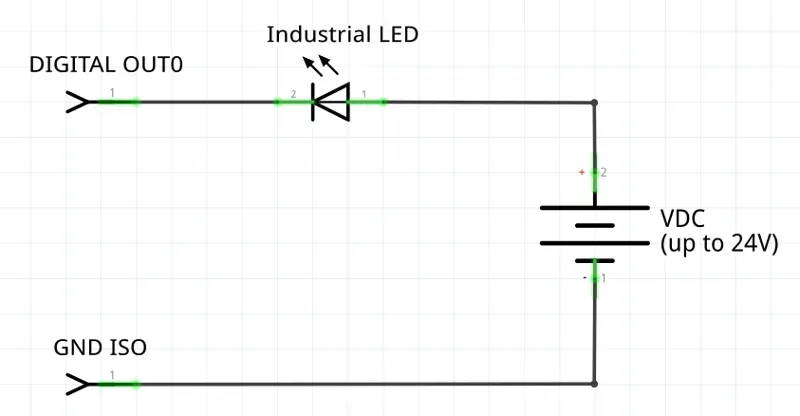
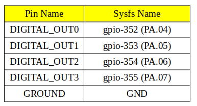
Find sysfs equivalent of the connected output pin from the table below. For this setup, it is DIGITAL_OUT0. After proper hardware connection with industrial LED, we can continue with the software side.
Then, set DIGITAL_OUT0 as output and control light state. To do this, you should use the commands below.
sudo sh -c "echo 352 > /sys/class/gpio/export"
sudo sh -c "echo out > /sys/class/gpio/PA.04/direction"
To short output:
sudo sh -c "echo 1 > /sys/class/gpio/PA.04/value"
To open output:
sudo sh -c "echo 0 > /sys/class/gpio/PA.04/value"
Thank you for reading our blog post.