

MILBOARD-AGXMAX Overview and Connector Definitions
WHAT YOU WILL LEARN?
1- The basic perspective over MILBOARD-AGXMAX
2- The definitions of each connector
ENVIRONMENT
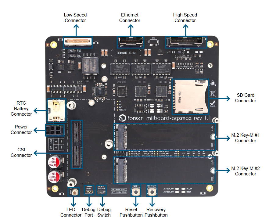
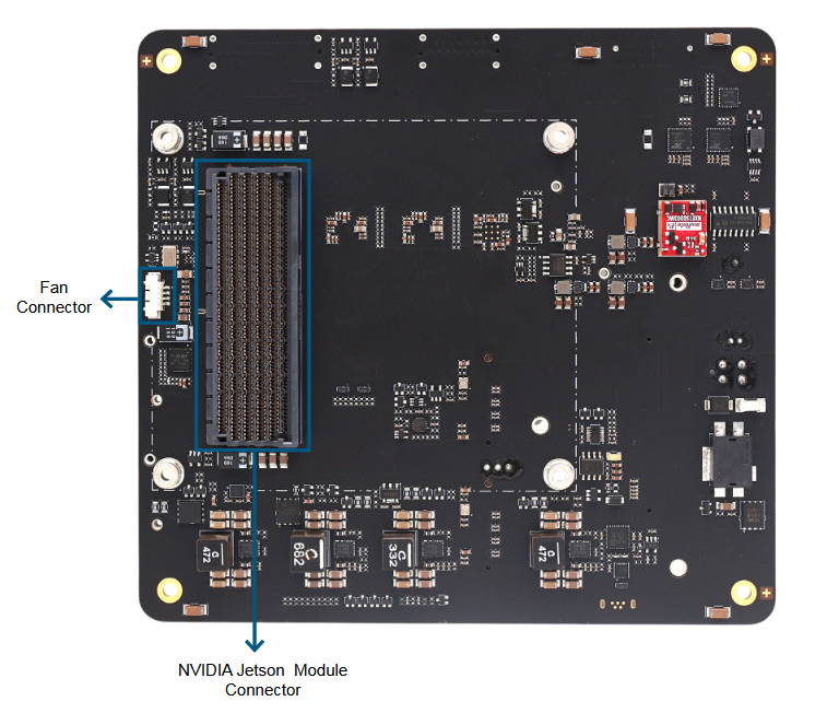
The Basic Perspective over MILBOARD-AGXMAX
TECHNICAL SPECIFICATIONS
Supported Modules
NVIDIA Jetson AGX Orin 32GB
NVIDIA Jetson AGX Orin 64GB
NVIDIA Jetson AGX Orin Industrial
Memory
32 GB 256-bit LPDDR5x
64 GB 256-bit LPDDR5x
Graphics Interfaces
1x HDMI 2.1
Interfaces
3x Gigabit Ethernet
1x 10G Ethernet
2x USB 3.2
2x USB 2.0
1x USB 2.0 (Serial Console)
2x CAN Bus (FD supported, 5Mbps)
4x RS232/422 (Software Configurable, Isolated)
8x Digital IO (3.3V Level, Isolated)
4x BNC (Configurable)
Other Features
TPM 2.0 Chipset for Enhanced Security
EEPROM, 6-Axis IMU & Temperature Sensor
RTC (Onboard external RTC chip for 10+ years battery life)
Wireless Communication
None
Power Supply
12-36 VDC (28 VDC Nominal)
Extension Sockets
1x Camera Expansion Connector (6x 2-Lane or 4x 4-Lane)
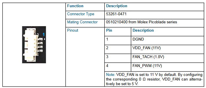
Fan Connector (11V Default, 5V Optional)
Mass Storage
64 GB eMMC 5.1 Flash
2x M.2 Key-M SSD Slot (occupied)
SD Card
Ambient Conditions
-40°C ... +85°C
Form Factor / Dimensions
150 mm x 140 mm, 139,2gr
Operating Systems
Ubuntu Linux 20.04
Ubuntu Linux 22.04
JetPack 5.x / 6.x / 7.2+
The Definition of Each Connector
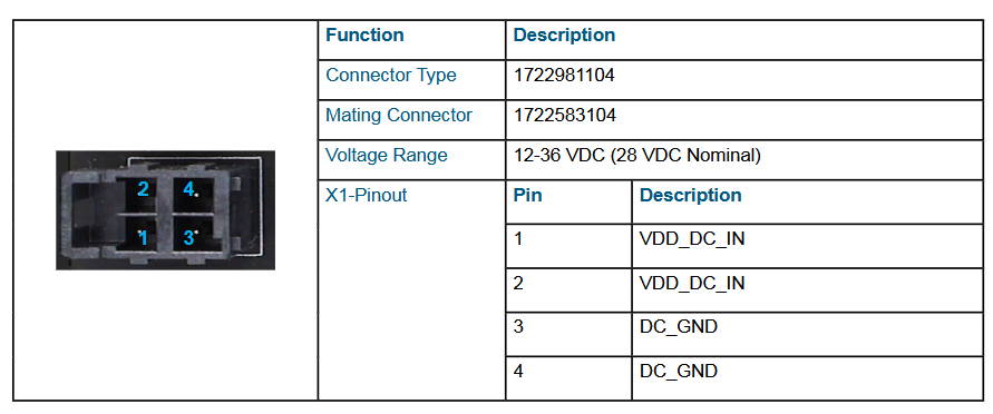
MILBOARD-AGXMAX Power Connector
The MILBOARD-AGXMAX implements 4-Pin Power Terminal Connector that accepts +12V to +36V DC power. The mating connector is "1722583104". The first andthe second pins are positive, third and fourth pins are negative.
MILBOARD-AGXMAX M.2 Key-M #1 Connector
The MILBOARD-AGXMAX implements M.2 Key-M1 Connectors (2280) for suitable modules.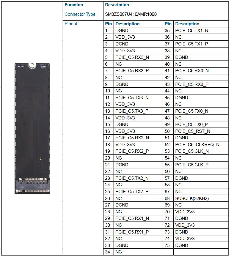
MILBOARD-AGXMAX M.2 Key-M #2 Connector
The MILBOARD-AGXMAX implements M.2 Key-M2 Connectors (2280) for suitable modules.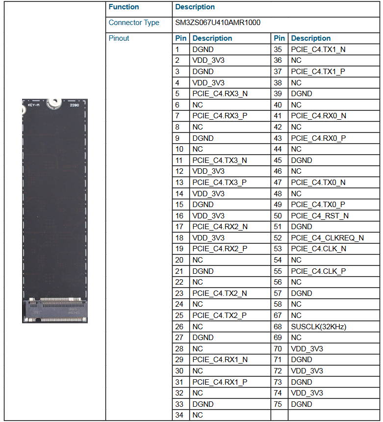
MILBOARD-AGXMAX Camera Connector
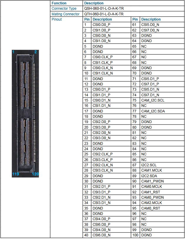
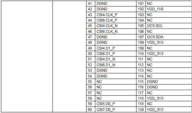
The MILBOARD-AGXMAX implements 16-lane camera connector for camera adapter boards. The connector model is "QSH-060-01-L-D-A-K-TR". The mating connector model is "QH-060-01-L-D-A-K-TR".
MILBOARD-AGXMAX High Speed Connector
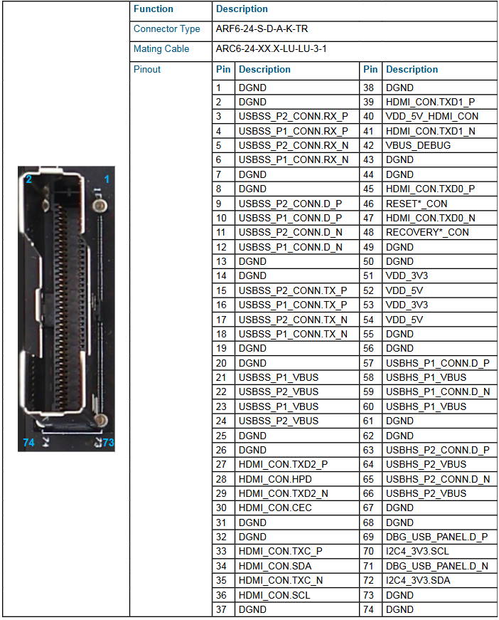
The MILBOARD-AGXMAX implements 74 pins connector. The Connector model is "ARF6-24-S-D-A-K-TR". The mating cable is "ARC6-24-XX.X-LU-LU-3-1".
MILBOARD-AGXMAX Low Speed Connector
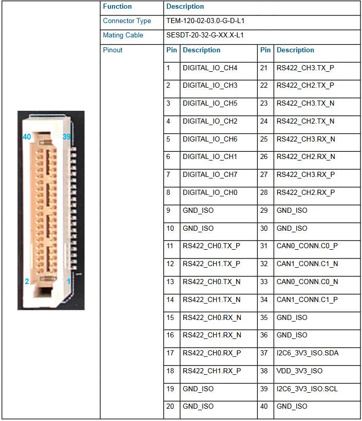
The MILBOARD-AGXMAX implements 40 pins connector. The Connector model is "TEM-120-02-03.0-G-D-L1". The mating cable is "SESDT-20-32-G-XX.X-L1".
MILBOARD-AGXMAX Ethernet Connector
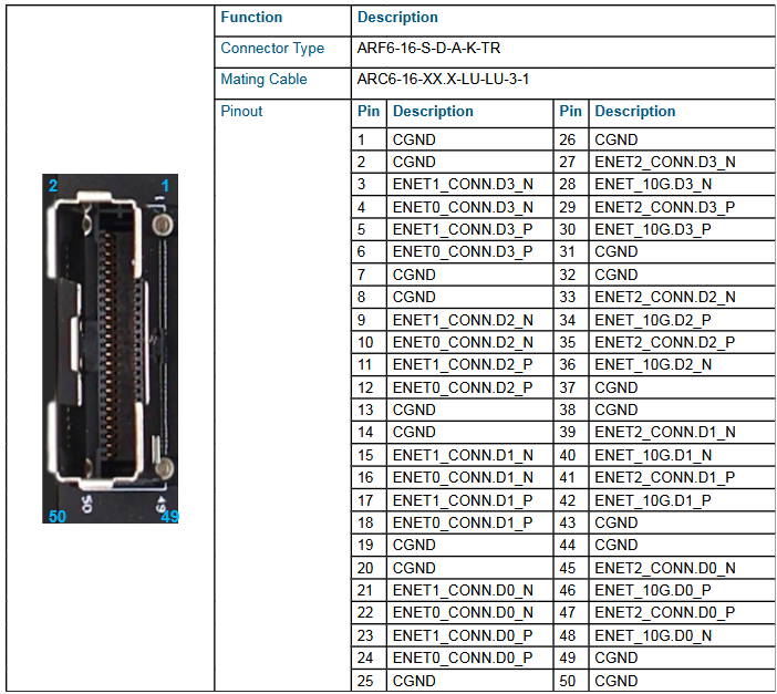
The MILBOARD-AGXMAX implements 50 pins connector. The Connector model is "ARF6-16-S-D-A-K-TR". The mating cable is "ARC6-16-XX.X-LU-LU-3-1".
MILBOARD-AGXMAX Fan Connector
MILBOARD-AGXMAX LED Connector
The MILBOARD-AGXMAX implements a TIM-02-F-SV-L-P model LED connector.

MILBOARD-AGXMAX Recovery Button
The MILBOARD-AGXMAX implements a recovery push button. Recovery button should be pressed with reset button at the same
time. After released reset button, recovery button should be pressed a little bit more (min. 250 ms).

MILBOARD-AGXMAX Reset Button
The MILBOARD-AGXMAX implements a reset push button.

MILBOARD-AGXMAX Debug Micro USB Connector
The MILBOARD-AGXMAX implements a Micro USB connector to access the module by using serial connection.

MILBOARD-AGXMAX Debug Switch
The MILBOARD-AGXMAX implements a Debug switch.

MILBOARD-AGXMAX RTC Battery Connector
The MILBOARD-AGXMAX implements a RTC battery connector.

